In early 2010, for a small variety of reasons, I built a small Arduino-based LED marquee. The project was initially meant as a group effort with friends from work; however, as circumstances worked out, I wound up designing, building, financing and ultimately keeping the device.
Since many people who initially intended to develop firmware and software for the marquee were relatively new to microcontroller programming, I chose Arduino as a backing platform because of its community support and trivial in-field reprogrammability, requiring no special hardware. The marquee as a whole is a fairly straightforward build, with the Arduino driving a series of four DE-DP016 boards from Sure Electronics. These form a 96x16 1-bit display. There is also a small power supply and a pair of female Arduino-switched USB A ports into which peripherals can be plugged. All of this is fitted in an acrylic case of my construction which has held up somewhat surprisingly well over time; my only gripe is that because of the open-sided design and the fact that grime sticks well to acrylic, it is a bit of a pain to clean the device properly when all the electronics are screwed in place.
The finished product, two and a half years later.
Power supply, Arduino, and LED matrices. On the bottom: DC input jack, power switch, and USB ports (power only, Arduino-switched).
Bottom ports and switch.
Full-frame video display from a C# host application (GDI+ rendering, scrolling tweets and Metacritic reviews about Papo & Yo).
The Circuit
Here is a circuit schematic. Nothing too mystical here - just a power supply, a USB port with switched power, and a connection to the DE-DP016 bus:
Circuit schematic.
A few notes:
CFILTPOWEREXT, CFILTPOWERINT and R2 are purposefully missing values because I was unable to pull down the real values I put in the circuit without taking the whole thing apart. However, the application notes for the 7805 voltage regulator lists CFILTPOWEREXT as being 0.33µF, and CFILTPOWERINT as 0.1µF. In my experience the 7805 is built like a tank and is probably not overly sensitive to these values.
I'm not 100% sure I used a 2N2222 as my transistor, and I'm quite unsure what value I used for R2; it was probably around 2 kΩ. If you replicate this circuit, use a value for R2 which will allow your transistor to saturate when driving your USB load. For example, if your load requires 200 mA at 5V and your transistor has a gain of around 100 at that point, you need a minimum of approximately 200/100=2 mA of base current. In practice, I would just throw the transistor onto a breadboard, wire it up to a switch and try out a few values for R2 until you are satisfied that your load can be driven properly. (With general-purpose and/or recycled transistors, there can be quite a gain variation between specific transistors of a given model.) To determine a good starting value for R2, you can simply divide your microcontroller's operating voltage by the required base current. At 5V, this means you could start with a 5/0.002=2500 Ω resistor and go down from there; lower resistor values will yield stronger base current. (This is really a back-of-the-envelope calculation to give a ball-park starting value; it neglects base-emitter voltage and many other tidbits.) Just be mindful of the absolute maximum DC current per I/O pin rating of the ATmega168/328, which is 40 mA; this means you should probably not go lower than 5/0.04=125
Ω, say probably 150
Ω to be safe. You shouldn't need anything near that much base current to saturate your transistor anyway.
You could also use a PNP transistor to switch the USB port without trouble; just make sure to change the firmware to set the D4 pin as a sink instead of a source.
I added D2 as a shunt diode because I need to drive inductive loads off the USB port. Even if you think you'll only drive purely resistive loads, it's not a bad idea to include one in order to protect the rest of your electronics - you never know what somebody will plug into a USB port, and it's cheap insurance.
The Software
Driven from a PC over serial port, the firmware itself supports a series of simple commands and can display text using a hand-created font. However, it is most frequently driven using ~29FPS full-frame video. This is easy to accomplish at 115200 baud, which in turn makes it simple to adapt most any PC-based rendering technology to the device. As seen in the video at the top of this page, by simply applying an intensity threshold to a bitmap in order to determine which LEDs to light up, OpenGL and GDI+ surfaces have been rendered to this device.
In 2010 I went on an extremely brief but equally intense Minecraft binge. Shortly afterwards I undertook the meta-challenge of writing some kind of network protocol analyzer (with much help from this page) to grok the state of the world and help me find resources. Sure enough, this evolved (devolved?) into a 3D overlay that allows the player to see through walls:
This not a hacked client. It is in fact a normal Windows desktop application, written in C#, that acts as a proxy between the regular Minecraft client and the server, a sort of voluntary man-in-the-middle attack:
MCPA (Minecraft Protocol Analyzer) sits between the Minecraft server and client.
The application intercepts all network traffic and parses it to build an internal representation of the Minecraft world. It displays three windows:
Minecraft protocol analyzer.
The top-left window is the setup window, where the user can configure the server address book and indicate which specific type of resource they would like to use as a target for the compass on the overlay. The top-right window is a debugging window that displays information about a configurable portion of the network traffic. And last but not least, the overlay window is a transparent, borderless window that always resizes and repositions itself to render atop the Minecraft client window:
The overlay window.
The overlay window displays a 3D view of "points of interest" near the player, namely specific types of ore and hazardous substances like lava. The 3D rendering is performed simply through GDI+, with a home-grown wireframe renderer. I guesstimated the projection parameters to more or less match what is seen in-game. You may have noticed in the video that there is a bit of a delay between the real game display and the update of the overlay. This is mostly due to the network processing delay; because the overlay is constructed from network data, MCPA has to wait until it receives the packets the client sends out when the player rotates her head.
The "HACK!" button on the top-left window serves as a debugging launchpoint for an experiment in packet injection, where MCPA manipulates client and server state. It is able to move and dig in a limited fashion; I had started writing an A* to auto-mine resources, but I eventually ran out of interest and moved to other projects.
I just noticed at the time of this writing that Mojang appears to have added encryption to their network feeds on the latest versions of Minecraft, which breaks MCPA. I would have to dig and see whether MCPA could be made to work at all despite this change, but it would probably require a fair amount of work.
(A note of intent: this software was never released, and it was only ever used on private servers with my friends and coworkers who are also game developers before it was possible to switch between creative and survival mode on a player-by-player basis and at will. They knew I was developing and using the software, and I always made sure to mine very far from the home base so as not to prevent them from finding materials for themselves when they so wished. The materials found using this overlay were used to benefit the server community and allow the group construction of elaborate structures; the goal was never to cheat and gain a personal edge of some sort or to grief other players.)
This is going to sound stupid, but one of the things I had always wanted to write as a kid/teen was a perspective-correct texture mapper. I'd written a few affine mappers before (good enough for some!), but had never really sat down to think about the math since the point in life where I had actually learned enough to work it out. So one idle afternoon in 2011, I spent a couple hours writing a truly bare-bones mapper. I spent zero time on corner cases; these show up as red pixels in the video.
2007 marked the beginning of my more serious tinkering with electronics. Among many other things, it's the year I bought my first pack of bulk LEDs, my first microcontroller, and my multimeter. Thus came to light (haha) my first electronics project:
Here is the long-delayed writeup for this project.
I wanted to start with a common enough project - building an RGB mood lamp. Sparkfun had just come out with their RGB LED bars, so I ordered a pack of 10 strips (30 RGB LEDs total) and set about designing the electronics. In retrospect, I should probably have used a smaller number of high-power LEDs - it would have made it easier to cram all the resulting electronics into the base of the paper lamp - but the LED strips make for a nice, wide, relatively uniform "area light".
As an LED driver, I selected the ULN2803 chip, which simply contains eight channels' worth of Darlington pairs. You can even wire up the channels in parallel to multiply the maximum current throughput.
My first idea didn't even involve using a microcontroller. So I got the chips, some pots, and connected up a simple prototype:
A simple dimmer circuit to try out things.
The red knob was connected to a potentiometer on the unamplified side of the circuit. It formed a voltage divider whose output was amplified by the ULN2803, which in turn drove the LED strip. The multi-turn trimpots you can see in the breadboard were there to adjust the biases and slope of the voltage divider, in order for the circuit to operate in the linear amplification region of the ULN.
Alternative view of the circuit; better view of trimpots.
As it turns out, I rapidly found out that the ULN is far easier to drive in saturation or shut-off mode. (I'm far from being an expert, but I'm guessing Darlington pairs in general probably require some serious care, both design- and application-wise, in order for both transistors to operate in their linear region.) While driving a single LED strip, well under the maximal rated load of the ULN2803, the heat dissipation in the ULN package was sufficient to cause the linear region of the transistors to shift. Thus, without even touching the input potentiometer, the colors on the LED strip would change rapidly and saturate quickly to white, in an uncontrollable fashion. Even funnier, by shooting compressed air at the chip to cool it down, I could get the colors to change back!
An easy way around this was to drive the ULN2803 with a pulse-width-modulated signal. This type of signal is trivial to generate with a microcontroller. (A harder way - for me at least - would have been to build some kind of oscillator whose duty cycle was controlled by a potentiometer, filter the output, and gamma-correct that in analog hardware... but since my analog design skills are quite weak, I opted for the MCU. Plus - programmability!) Coincidentally, with no microcontroller programmer in my possession yet, I had recently ordered an Arduino, and it arrived around the time I made this discovery.
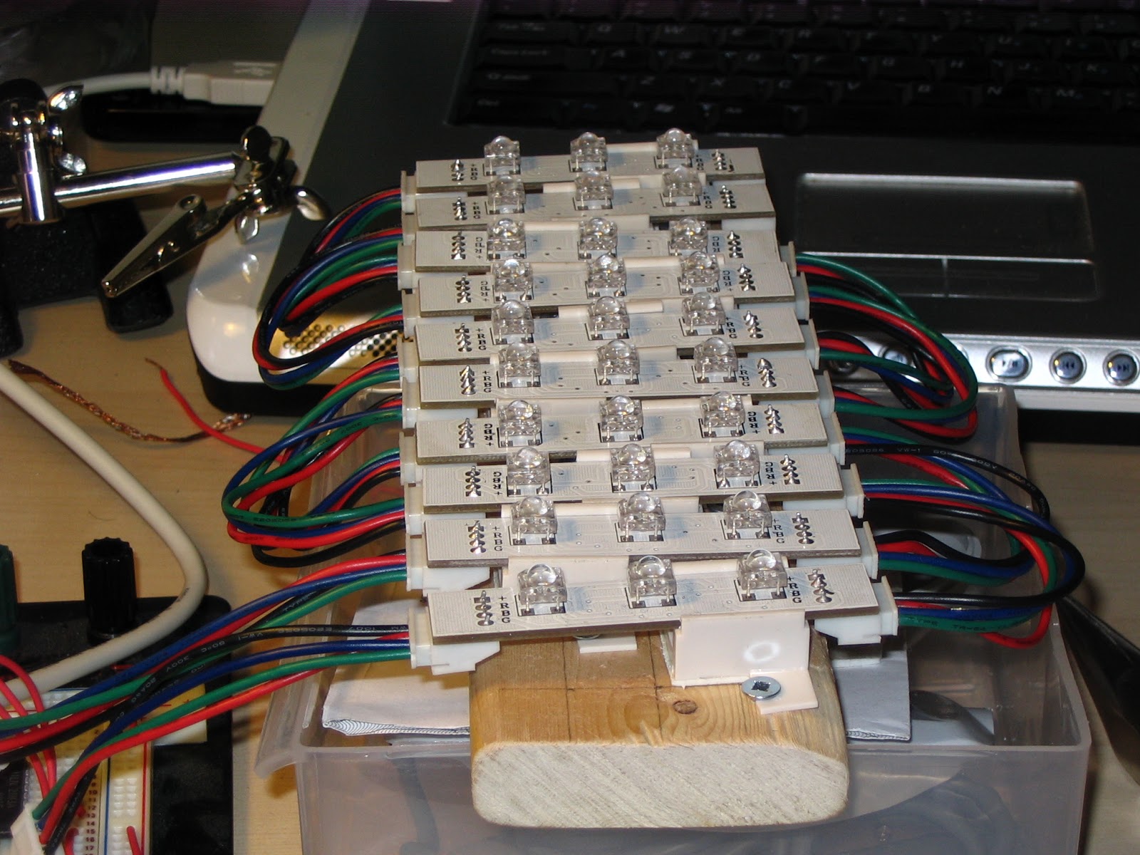
In order to test out things with all LED strips, I buit a little rig to hold them together:
Working out where all the screws need to go to keep the LED mounts in place.
The Arduino, wired to read the RGB pots and drive the RGB LEDs through the ULN2803.
Same.
Close-up of the LED rig.
Power up!
The Arduino setup, with a custom power supply. Nothing too fancy here.
Things seemed to be working nicely, so I moved the ULN to the power supply perfboard. I first planned out the layout using my old friend Paint.NET to make sure things fit properly. (I also use it as a checklist by crossing out traces I've soldered in place. This design is not particularly complex but on more fleshed-out boards it can be a lifesaver.)
Figuring out what goes where.
Lights on!
The final knob wiring.
Moving the ULN2803 to the power supply perfboard.
This was a turning point in the project. Though I felt it was cool to have an RGB mood lamp, I rather thought using a microcontroller simply to do PWM was overkill, even though it was also doing simple gamma curve math to normalize the LED output colors. And I figured, well, it's already part of the system, so what else could I do with it? The first obvious answer was to implement automatic color cycling. I did this and used the RGB knobs to control the brightness, saturation and speed of the cycling.
I also thought it would be really cool to have the lamp respond to music somehow, but I was still a bit analog-shy after being beaten on the head with the topic in school. I began by adding MIDI in support, using a 6N138 optoisolator. I made it so that when Note On signals were received, the LEDs would light up with a brightness related to the volume of the notes. Here's the MIDI In stage schematic. I believe it originated from Tom Igoe's most excellent ITP materials; though I can no longer locate the original page, the schematic is reproduced here.
Arduino MIDI Input stage.
It was very cool to see some interactivity there! But I think what I ultimately wanted was to feed arbitrary music to the lamp. Thus, I decided to wire up an analog signal path and see if I could coax the required signal treatment out of the Arduino to be able to send bass to the red channel, mids to the green channel and highs to the blue channel. Here is the resulting circuit schematic. Once more I believe the biasing portion was somehow gleaned from Tom Igoe's ITP stuff, but I am unable to find the exact original source.
Arduino stereo analog input stage.
This circuit mixes the left and right channels together and biases the whole thing by 2.5V so it centers around the Arduino's analog input range.
Testing MIDI and audio input.
Idem. You can see the breadbord layout with an RBBB Arduino.
More testing.
The rest was just writing software. Conceptually, the analog input stuff is fairly simple. The analog signal is read with 10-bit precision, and is first fed through a very wide high-pass filter to block the DC component. Then, it is fed to three separate IIR filters. The first is a low-pass filter for the red channel; the second, a band-pass filter for the green channel; the last, a high-pass filter for the blue channel. Each filter is "doubled up" on itself to sharpen the rolloff and reduce the overlap between the frequency ranges of each filter. I tuned the filter cutoffs by creating a sine wave patch on my Yamaha DX-100 and feeding that to the lamp to see what color each note triggered.
In practice it took some fiddling to get everything running zippily. Fixed-point math took care of a lot of the performance woes. I also wound up writing a simple custom multiplication routine in assembler to multiply two 16-bit numbers together into a temporary 32-bit buffer, to avoid overflow, then shift back to fixed point before storing the result. (The compiler normally requires 32-bit source values to multiply into a 32-bit destination buffer, but full 32-by-32 multiplies were useless work that wound up being prohibitively expensive.)
I still have the code for all this, and would be glad to share it, but it is far from building on the latest Arduino platform. If there is interest, I would be glad to clean it up and modernize it a bit; just let me know in the comments or e-mail me!
After I was sure everything worked, it was time to embark on the final step of the process... physical fabrication. I think the pictures do a better job than text at explaining.
Final power supply and amplification board.
Laying out the logic and input board.
Final Arduino and input board.
Cutting some holes.
All parts, ready for final assembly.
Cramming everything in there!
Underside.
The boards are held in place with Velcro.
Logic board in place.
Final result - power, mode switch, potentiometers.
In 2010 I got tired of continuously having to wire up breadboard power supplies. I found I often wanted to just prototype something quickly with a few parts I had lying around, but I frequently gave up before starting because I was too lazy to fish out and wire up yet another LM317 or something. Thus, as is the fashion when nothing too serious is required for a benchtop power supply, I put together a small ATX power supply breakout box with an adjustable voltage regulator.
I began by planning out a simple circuit. I put a voltmeter on the adjustable voltage branch as well as an ammeter on the common ground:
Circuit for the ATX power supply breakout box.
I laid out the faceplate elements on cardboard to make sure things fit as intended:
Mocking up stuff on leftover cardboard.
Cutting the cardboard to the correct dimensions.
Final mockup.
Then, I carefully transferred the markings to some acrylic sheets I had scored and snapped to size:
Transferring the layout markings from graph paper to acrylic faceplate.
Making sure things line up.
Then, I drilled all the required holes and openings on a drill press borrowed from my dad. I believe I used a sheet metal nibbler to square out the edges of the doorway-shaped holes, for the meters.
The cutouts. (This picture was actually taken after I removed the protective film, later on.)
Cutouts.
Then, I test-fit everything to make sure things would line up properly, that there was enough space, etc.:
Testing for fit.
Will it close properly?
Faceplate will look OK it seems.
Since the test fit looked promising, I went ahead, peeled the protective film from the acrylic and assembled everything:
Wiring up the faceplate.
More faceplate action.
Adding the actual guts of the breakout box.
And it turned out great:
Looks good.
From up high.
From the side
Underside.
Off.
ATX supply on in standby, not delivering power yet. (That's the red LED.)
Final result, delivering power as indicated by the green LED. In case of panic just slam the safety cover shut.
In the end, everything works great except the ammeter. That was a dumb mistake; I didn't test it in-circuit before putting everything in place, and I didn't realise that it required special wiring. (I never looked into it but I suspect it actually acts as a voltmeter, and you have to wire it up across a specified value of resistor for it to work properly.)
After making use of this thing for a couple of years, I might say a couple of things about the design:
Though I didn't think the zipties around the back would be sufficient to hold the meters in place, they are still there in 2012 and the meters haven't moved.
On the other hand, it was hard to find an inspired way to hold the molex breakout in place; it sucked on day one and it still does today. (As you might be able to tell from the pictures I built a sort of acrylic clamp. Won't do that again, the connector keeps slipping out, the acrylic bends, etc.)
Instead of using three nuts per screw, I now use standoffs I cut myself from 1/4" plastic water piping.
The safety cover on the switch came in handy many times. Because it's spring-loaded, it's much easier to slam the thing shut than to flick a pretty rigid toggle switch.
Acrylic is too fragile a material for something that will be manhandled like this; though it hasn't happened yet, I'm always afraid I'm going to break the thing.